
Choosing the right Analog Converter starts with the signal, not the product label. Is the circuit converting a sensor’s voltage into digital data, or turning digital values into an analog output? That distinction shapes the required architecture. A temperature sensor may produce a slow, small signal, while an audio circuit must preserve a much wider range of frequencies. Different jobs call for different trade-offs.
Look closely at input or output range, resolution, accuracy, sampling rate, bandwidth, and noise. These specifications are related, but they are not interchangeable. More bits do not automatically mean more useful precision. Check the full signal chain, including reference voltage, power supply, interface, and expected operating conditions. A converter that looks suitable on paper may still perform poorly if its input is noisy or its reference is unstable. Small details matter.
The datasheet is a strong starting point, not a guarantee of results in your design. Compare specifications under conditions close to your own, and test a prototype when practical. A bench measurement can reveal noise, settling time, or layout issues that a headline figure misses. It is easy to focus on one impressive number and overlook the rest. The best choice is usually the converter that meets the real requirements with dependable performance and reasonable design effort—not simply the most advanced or expensive option.
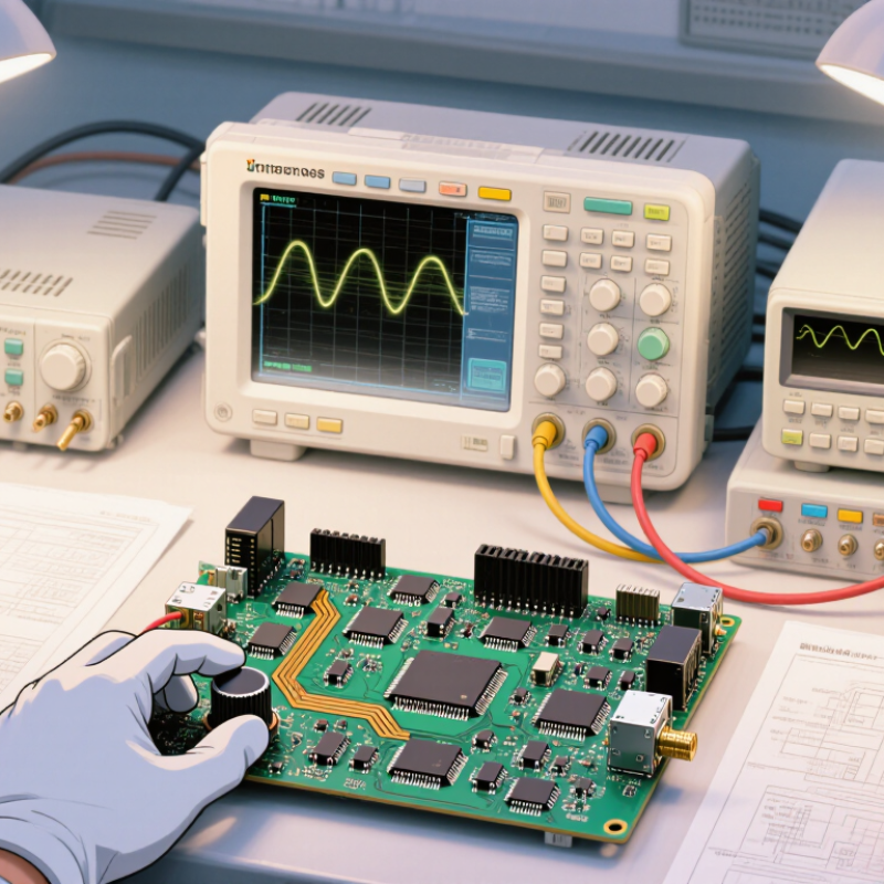
Define the converter’s role before comparing specifications. An ADC samples an analog input and encodes it as digital values. A DAC converts digital codes into an analog voltage or current. That distinction matters. For example, an ADC can capture a microphone’s changing waveform, while a DAC can feed a reconstructed waveform to an output stage. Match the converter to the signal’s direction, range, and speed. A sensor that changes slowly may not need the same sampling rate as a rapidly varying signal.
Resolution and sample rate deserve attention, but neither works alone. Check input range, noise, latency, and the analog circuitry around the converter. I still find it easy to focus on bit depth and overlook bandwidth. That can lead to a poor fit. The WSTS Spring 2024 Forecast projected 2024 analog semiconductor sales of about $79.3 billion, reflecting the broad role of analog electronics across applications. This market figure is context, not a guide to selecting one converter.
Tips: Start with the signal you need to measure or produce. For an ADC, check the source’s bandwidth and required sampling rate. For a DAC, check the output load and required settling time. Leave practical margin; real circuits are rarely as tidy as a datasheet example.
When choosing an analog-to-digital converter, resolution tells you how finely it can divide its input range. A 12-bit converter produces 4,096 possible codes; a 16-bit converter produces 65,536. More codes, yes. Across a 0–5 V range, one ideal 12-bit step is about 1.22 mV. A 16-bit step is roughly 76 microvolts. That finer spacing can reveal small sensor changes, such as a slow temperature drift or a slight pressure shift.
But a smaller step does not guarantee a more accurate reading. Noise, reference-voltage stability, input circuitry, and converter linearity all affect the result. If the sensor signal jitters by several millivolts, a 16-bit output may simply record that jitter in greater detail. On a real bench, grounding and wiring can matter more than the extra bits. It is easy to overvalue the headline number. Check the converter’s effective resolution and noise specifications, then compare them with the smallest signal change your application must detect. A careful 12-bit design can outperform a poorly supported 16-bit one.
Choosing an analog-to-digital converter starts with the signal’s frequency range. For a baseband signal, find its highest meaningful frequency. The Nyquist limit says the sampling rate must be at least twice that frequency. A 10 kHz signal therefore needs a minimum rate of 20,000 samples per second. That is a floor, not a comfortable target. At exactly twice the frequency, small timing errors or unwanted high-frequency noise can distort the captured signal. An analog anti-aliasing filter helps remove frequencies the converter cannot represent.
Tips: Check the filter’s cutoff and transition band before setting the rate. Leave room above the theoretical minimum. For a 10 kHz signal, 25,000 or 40,000 samples per second may be more practical, depending on the filter and required accuracy. Verify with a test tone.
Higher rates are not automatically better. They can increase data storage and processing needs, while offering little benefit for a narrow, clean signal. A quick bench test can reveal whether the chosen rate preserves the waveform’s shape and amplitude.
One detail is easy to overlook: real signals often contain noise beyond their stated bandwidth. The filter and sampling rate should account for that, even when the first estimate seems adequate.
An ADC’s bit count describes its output code range, but it does not tell the whole accuracy story. Effective number of bits, or ENOB, estimates how many bits remain useful when noise and distortion are included. Calculate it from SINAD: ENOB = (SINAD − 1.76 dB) / 6.02. SINAD is the signal-to-noise-and-distortion ratio, measured in decibels. The constants assume a full-scale sine wave and an ideal converter. That context matters.
For example, a measured SINAD of 74 dB gives an ENOB of about 12 bits. A nominal 16-bit converter can therefore deliver roughly 12 effective bits under that test condition. Numbers shift with input frequency, sampling rate, signal amplitude, and measurement setup. On a bench, a clean sine wave and careful grounding help reveal converter performance; a noisy source can blur the result. Check the test conditions before comparing specifications.
Use ENOB to judge whether a converter can resolve the changes your application needs, not as a universal accuracy guarantee. A sensor system with slowly changing inputs may tolerate less bandwidth, while a fast waveform measurement can expose distortion. I would also check offset, gain error, and input range separately; ENOB does not replace those checks. It is easy to lean too hard on one number. Compare measurements made under similar conditions, and leave margin for the actual circuit.
A converter can meet every resolution target and still fail in the system. Check the host interface, available pins, clocking, and data rate before comparing headline specifications. SPI is simple for slower control and sampling; faster designs may need LVDS or a serial link. JEDEC JESD204C specifies lane rates up to 32 Gb/s, but that speed brings tighter clocking and layout demands. More speed is not always better.
Check supply rails and reference requirements against the actual board. A reference with low noise and drift helps preserve accuracy, but it must suit the converter’s input range and load. Review startup behavior, decoupling, and reference-drive needs. A small mismatch can produce settling errors that are easy to miss in a schematic. IEEE Std 1241-2010 describes ADC test methods, including measurements tied to noise and effective resolution; use comparable conditions when assessing specifications.
A practical bench check helps. Measure current draw during conversion, then inspect reference stability near the device pins. Leave margin for temperature and supply variation. Datasheet figures can look reassuring. They are not the whole story. I’d also verify the interface with the intended processor and firmware; this step is sometimes left too late. The right part is the one the complete system can power, clock, communicate with, and measure reliably.